Installing FreeBSD on the Asustor Lockerstor 10 Gen3 (AS6810T)
A note on authorship: this article was written with AI, not by AI. The installation was done hands-on, mistakes included. Notes were taken along the way with AI assistance, then shaped into this document. The content was proofread and validated against the actual experience. Without AI, this NAS would be installed but I wouldn't have had the time to write these findings — so don't blame the AI for this article!!!
A note on photos: this article was written after a successful install. The drives are in, the system is running, and nobody is pulling NVMe sticks out to re-stage assembly photographs. Any photos of the mounting or riser setup in this article were taken outside the context of the live install — treat them as illustrations, not step-by-step documentation.
A note on the audience. This guide assumes you are comfortable with FreeBSD or another *nix on the command line, and that you have chosen this path deliberately — over ADM, TrueNAS SCALE, or TrueNAS CORE — because you know what you want from the OS. *Nix newcomers will find the work daunting and probably should not start here. *Nix veterans who routinely build their own kernels and write drivers will find some of the explanations basic. The sweet spot is the experienced FreeBSD/Linux user who has not previously had to fight a closed-firmware appliance into running a non-vendor OS — that's where this article will save you the most time.
A note on time. Not counting the time waiting for ordered hardware (riser, GPU, USB-Ethernet adapter), the actual install — debugging and discovery included — took less than a day. Your mileage will vary based on background; how much each problem feels like work depends on how many similar problems you've solved before. AI was useful as a diagnostic partner — it accelerated the "what's the failure mode here?" loop substantially — but the work of filtering hallucinations, deciding which replacement hardware to order, and choosing what to actually test stayed firmly with the human. Treat any AI in this kind of project as a fast-talking junior engineer: useful for narrowing the search space, never trusted on the final call.
Bonus: sanitized hardware dumps (pciconf -lv, dmesg, dmidecode, acpidump, ZFS layout, sensor sysctls, and 20+ others) are published as a redacted bundle alongside this guide. See the Hardware reference data section near the end.
Contents
(Anchors will resolve once the document is rendered as HTML.)
The setup — annotated
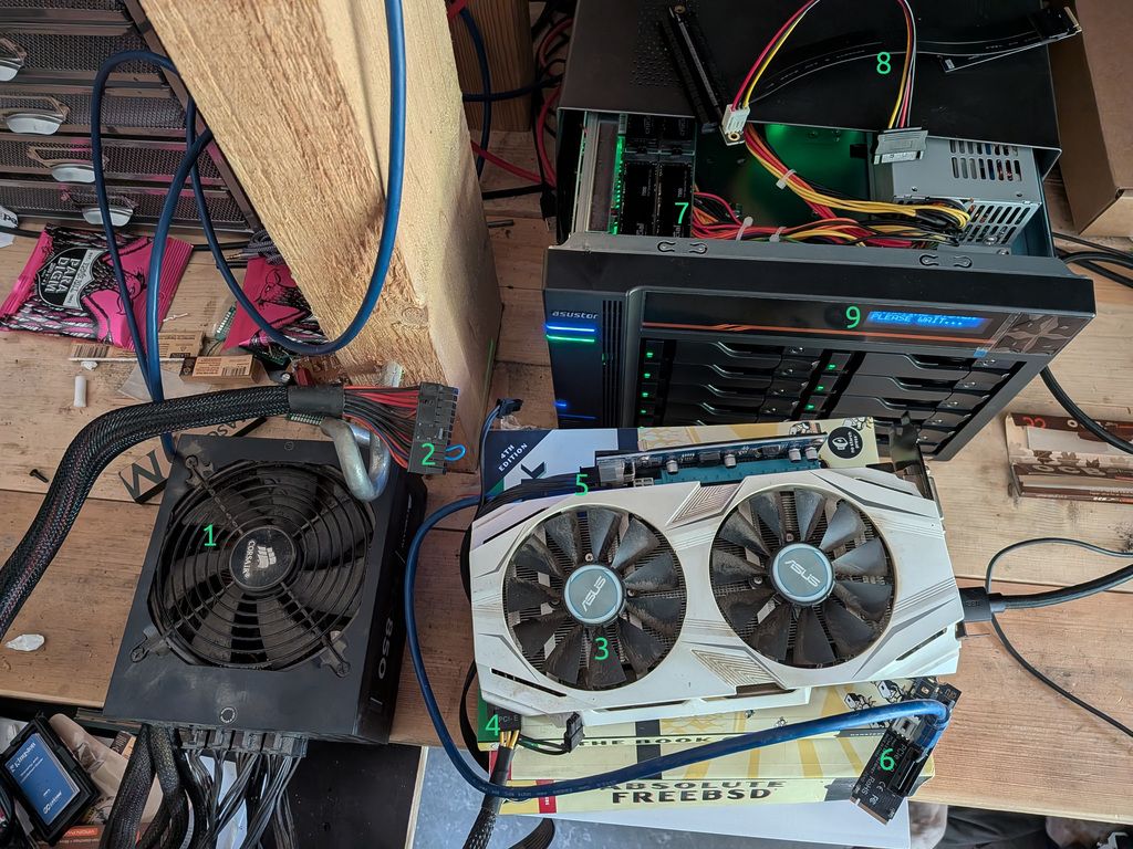
The full install rig, everything laid out on the bench. Numbers referenced throughout the article:
| # | What it is |
|---|
| 1 | External Corsair ATX PSU — powers GPU and riser, completely independent from the NAS's internal PSU |
| 2 | The PS_ON short — 1.5 mm² wire bridging green to black on the 24-pin, tricking the PSU into running standalone |
| 3 | ASUS GTX 1060 — the GPU that finally worked (dual-fan, requires aux power, UEFI VBIOS) |
| 4 | PCIe power cable from PSU to GPU aux connector — must be the PCIe/VGA cable, not CPU/EPS |
| 5 | PCIe riser board — from an old mining rig; the blue ribbon cable carries PCIe 1x signal to the NVMe adapter |
| 6 | M.2-to-PCIe adapter — plugs into NVMe slot 3 (with NVMe 0 and 1 occupied by the system mirror), converts it to a PCIe slot for the riser |
| 7 | NVMe slot 3 inside the open NAS chassis — where the riser adapter is inserted |
| 8 | The riser that didn't work — likely due to SATA power being insufficient for the 12 V GPU rail |
| 9 | The front LCD panel: "PLEASE WAIT..." — your best friend during BIOS entry attempts |
Note the "Absolute FreeBSD" book pressed into service as a GPU stand. Appropriate.
Difficulty rating: ~8/10. Each individual problem is solvable in 5–60 minutes. The difficulty is that they chain together, and most people stop at the second or third one. This article documents every obstacle encountered so you can walk straight through instead.
Introduction
The Asustor Lockerstor 10 Gen3 (AS6810T) is a high-end 10-bay NAS built around AMD's Ryzen Embedded V3C14 — a fast, power-efficient processor with ECC DDR5 support, PCIe 4.0, and fast networking. On paper it is almost perfectly suited as the foundation for a serious ZFS-based FreeBSD server: lots of drive bays, NVMe slots for a boot mirror and metadata, and 5 GbE networking. ASUSTOR even produces an official TrueNAS install video for the series.
In practice, the path to a working install is mined with quirks that aren't documented anywhere obvious. ASUSTOR's video covers the happy path and glosses over nearly every failure mode you'll actually encounter. Community resources for this hardware barely exist — the Gen3 series only launched in late 2024, and detailed FreeBSD-specific notes are essentially nonexistent.
This article documents a complete real-world installation experience. Every obstacle is here, in the order you're likely to encounter it, with the underlying cause explained and the workaround spelled out. If you follow along carefully, you should be able to get FreeBSD installed and booting on an AS6810T without any unpleasant surprises.
The hardware at a glance
Before diving into the problems, it helps to understand what you're working with.
CPU: AMD Ryzen Embedded V3C14 (Zen 3+ "Rembrandt" cores, PCIe 4.0, no integrated GPU — more on this in a moment).
RAM: 16 GB ECC DDR5 SO-DIMM as shipped. The slot layout is worth confirming physically on your unit — it may be 1×16 GB or 2×8 GB. The machine supports up to 96 GB and accepts a second matching ECC DDR5 SO-DIMM. For serious ZFS use, upgrading to 32 GB before doing anything else is strongly recommended. 32 GB is enough for normal ZFS workloads including a large RAIDZ pool; just don't enable global deduplication (more on ZFS choices later).
Storage bays: 10× SATA (3.5"/2.5", hot-swap), and four M.2 NVMe slots (PCIe 4.0).
Networking: two 10 GbE ports (AMD integrated) and two 5 GbE ports (Realtek RTL8126). More on why only two of these four will work reliably under FreeBSD.
Boot storage: internal eMMC (~7 GB) running Asustor's ADM firmware. This stays in place even when you install FreeBSD.
Expansion: one internal PCIe slot — but with a critical catch that eliminates it from most install scenarios.
The first big problem: there is no display output at all
This is where most people stop before they even start. The AS6810T has no HDMI port, no DisplayPort, no VGA — there is no built-in display output of any kind on the chassis. Unlike most NAS units you've seen, this one truly has no display path at all.
The reason is that AMD's Ryzen Embedded V3000 series — which includes the V3C14 in this machine — shipped without integrated graphics. Most V1000 and V2000 SKUs had Vega iGPU; V3000 dropped it entirely. The V3C14 is genuinely headless silicon. There is nothing to plug a monitor into because there is no display engine on the chip.
The obvious solution — "just stick a GPU in the PCIe slot" — runs directly into the second big problem.
The PCIe slot is mutually exclusive with all four NVMe slots
The AS6810T has one internal PCIe expansion slot. You might reasonably expect to install a cheap GPU there for installation purposes, run the install, then remove the GPU after. This doesn't work.
ASUSTOR multiplexes the PCIe lanes between the four M.2 NVMe sockets and the single internal PCIe slot. Which one gets lanes is controlled by a software toggle in ADM called "PCIe Mode Switcher." Only one mode is active at any time:
- M.2 mode: all four NVMe slots active, internal PCIe slot dead.
- PCIe mode: internal PCIe slot active, all four NVMe slots dead.
The default is M.2 mode. This means that if you want to boot from NVMe drives (which you almost certainly do), the internal PCIe slot is unavailable, and you cannot use it for a temporary GPU.
The workaround is to bring the GPU outside the chassis entirely using an M.2-to-PCIe riser cable. The riser plugs into one of the NVMe M.2 sockets, the GPU hangs off the other end via ribbon cable outside the machine on the bench, and you use it only for the install. This is completely viable but introduces its own chain of problems.
This also explains concretely why a 4-drive NVMe RAIDZ at install time is impractical: one of the four M.2 slots is occupied by the riser during the entire install procedure. You effectively have three slots available for drives, not four.
The riser rabbit hole
Getting a riser that physically fits
The riser fit is actually not as difficult as some guides make it sound. There is roughly 3–4 cm of clearance above the M.2 sockets — not cavernous, but enough for a ribbon-cable riser to sit and exit cleanly. The practical approach is simply to leave the case open on the bench for the duration of the install, with the GPU resting outside the chassis on the ribbon cable. This is not a permanent setup — it's a one-time install fixture, and it works fine. (→ photo: items 5, 6, 7)
The key requirements for the riser:
- Flexible ribbon cable. Rigid PCB adapters that plug directly into the M.2 slot without a cable are not useful here — the GPU needs to be outside the box.
- A separate 12 V power input on the riser PCB — SATA, Molex, or 6-pin PCIe. More on this below.
Getting a riser that actually powers the GPU
This is a subtler problem. An M.2 slot only supplies +3.3 V at approximately 3 A — about 10 watts maximum. Any real GPU also needs +12 V, regardless of whether it additionally has an aux 6-pin or 8-pin connector. Many cheap "passive" M.2-to-PCIe adapters — the tiny rigid ones with no extra power input — simply don't provide +12 V to the slot, and any GPU connected to them is completely inert: no fan, no LED, nothing.
You need a riser with a separate power input on the PCB itself — typically a SATA power connector, a 4-pin Molex, or a 6-pin PCIe input. Mining-style ribbon-cable risers almost always have this. Confirm before purchasing.
Critical rule: the riser power input AND the GPU's aux power connector must both be fed from the same external PSU. Connecting them from two different PSUs (for example, tapping riser power from a separate machine's PSU and GPU aux from another unit) creates ground-loop conditions between the two power supplies that can destroy the GPU instantly. Use one external ATX PSU for everything GPU-related. The NAS's own internal PSU is not a candidate anyway — it has no free SATA power leads, and even if it did, mixing it with an external PSU for the GPU is exactly the ground-loop trap described above. (→ photo: item 8 shows the riser that failed — it was fed via SATA power borrowed from another machine on the bench, which proved insufficient for the 12 V GPU rail)
Powering an external PSU on the bench
To power a GPU during install, you need an external ATX PSU running without a motherboard attached. ATX PSUs only supply their main rails after the motherboard pulls the PS_ON signal (green wire, pin 16 of the 24-pin connector) to ground. With no motherboard, you do it manually.
Bridge the green wire to any black wire on the 24-pin connector. (→ photo: item 2) A paperclip works in a pinch. Fine breadboard/DuPont jumper wires are too thin for reliable contact at the connector pins — they tend to not make solid contact and can cause the PSU to cut out unexpectedly. What worked well: a short length of 1.5 mm² electrical cable (standard household wire), stripped at both ends and bent into a U-shape bridging the two pins. Solid, stays in place, good contact.
Two important facts about this:
- The short stays in place the entire time the PSU is running. It's a level signal, not edge-triggered. Remove the short and the PSU shuts off. Insert the jumper first, then flip the power switch. Remove the switch first before the jumper.
- Some PSUs need a minimum load to start. If yours powers off immediately after starting, plug a SATA hard drive or a case fan into a Molex connector to give it 3–5 W of load.
The first attempt used a SATA power connector borrowed from another machine on the bench to feed the riser. Two problems with that: SATA connectors don't supply the aux 6-pin current a real GPU needs, and mixing PSUs is exactly the ground-loop trap described in the previous section. A single dedicated external PSU with the PS_ON short — feeding both the riser and the GPU aux from the same unit — fixed both.
Choosing a GPU that will work
Not every GPU works on the AS6810T, even with a properly powered riser. The firmware is UEFI-only with no CSM (legacy compatibility mode). This silently disqualifies a large fraction of cheap GPUs.
The VBIOS problem
Many budget GPUs — particularly generic GT 710 and GT 730 variants — ship with legacy PC-BIOS-only VBIOS. They have no UEFI GOP driver. When the AS6810T's TianoCore firmware tries to initialize the display, it has no way to talk to a legacy-only card, so nothing appears on screen.
The deceptive part: the fans still spin. With insufficient or correct power, the card does a self-test at startup — you'll see the fans move. This makes it look like the GPU is alive. It is, electrically. But spinning fans do not mean the GPU is producing display output. A card with a legacy-only VBIOS can be perfectly powered and completely useless on UEFI-only firmware. Don't use fan spin as confirmation of a working display path.
A GT 730 was tried first — powered riser, fans spinning, zero display output. This is exactly the VBIOS problem in action.
GPUs that work (confirmed empirically or known to carry clean UEFI VBIOS):
- NVIDIA Quadro P400 / P600 / P620 (Pascal, slot-powered, 30–40 W)
- NVIDIA T400 (Turing, slot-powered, ~30 W)
- GTX 1060 / 1070 / 1080 (Pascal, requires aux power, VBIOS is fine)
- AMD RX 6400 low-profile (RDNA2, slot-powered, ~53 W)
GPUs to avoid:
- Generic GT 710 / GT 730 DDR3, anything pre-700-series NVIDIA
- Any "fanless OEM" card pulled from a refurbished prebuilt — frequently legacy VBIOS
- AMD Radeon HD 5xxx / HD 6xxx
A GTX 1060 was used successfully. (→ photo: item 3) This card requires a 6-pin aux power connector — both the riser's power input and the 1060's aux connector were fed from the external PSU's dedicated PCIe power plugs (→ photo: item 4) (not CPU/EPS cables — see below).
The aux power cable pitfall
Modular PSUs ship with multiple 8-pin connectors that are physically identical but have different pinouts. The cables labeled CPU or EPS look exactly like the cables labeled PCIe or VGA, but they are NOT interchangeable. Plugging a CPU/EPS cable into a GPU's 8-pin connector puts +12 V on pins that the GPU expects to be ground, destroying the card instantly.
Always verify: use only the cable labeled PCIe or VGA on the PSU end for GPU aux power. If you're using a Corsair modular PSU, the cables are not even cross-compatible between product series (RM, HX, AX) or between revisions. Use only the cable that came with your specific PSU.
Verifying the display actually works
Before going hunting for the BIOS key, you need to know what "display working" looks like on this machine — because there is no firmware splash, no POST messages, and no progress bar to confirm anything. The screen stays black through the entire BIOS/POST phase, which lasts several minutes on a fully populated chassis.
POST on a fully populated machine takes a while. With 10 SATA drives, 4 NVMe drives, and 32 GB ECC RAM going through their checks, several minutes between power-on and a usable BIOS prompt is normal — and probably driven more by the amount of hardware to enumerate and the ECC memory training pass than by the firmware itself. A bare-bones config (single NVMe, 16 GB, no SATA disks) almost certainly POSTs faster, but I haven't measured that. Patience is the right tool here. Power-cycling because "nothing is happening yet" is the most common way to convince yourself the hardware is broken when it isn't.
What you'll actually see on screen, in order:
- Monitor wakes from sleep (the no-signal indicator disappears) — early in POST.
- Black screen for several minutes — POST is running. The display works; the firmware just isn't drawing anything to it. This is the BIOS window — F2 only works during this phase.
- A steady
_ appears in the top-left — too late. The underscore means POST has finished and ADM has started loading. If you see the _ and you haven't pressed F2 yet, you've missed the window. Power off and try again.
So: the _ is not a "display alive" indicator — it's a "you missed the BIOS window" indicator. Display verification has to come from somewhere else.
The real way to verify the display works is to enter the BIOS. If F2 succeeds, you have both a working display and a working BIOS path. If a full POST cycle elapses (5+ minutes from power-on) and F2 doesn't take you into Setup, and the _ then appears, the display path is fine but your BIOS-key timing was off — retry with the rhythm described in the next section.
Diagnosing what you do see during the black-screen phase:
- Monitor wakes, then
_ eventually appears → display path is fine. F2 just didn't land in time. - Monitor wakes, but no
_ even after 8+ minutes (first boot of a new build) → GPU enumerated and powered but not initializing video output. VBIOS incompatibility (legacy BIOS-only card on UEFI firmware), wrong aux power cable (CPU/EPS into a PCIe socket), or the card itself is dead. - Monitor wakes, but no
_ after 8–10 minutes (after a reboot of a previously-working setup) → almost certainly a GPU stuck in a half-initialized state. This happened when the NAS was rebooted but the external PSU feeding the GPU was not power-cycled at the same time. The card retains state from the previous boot and the firmware can't bring it back up cleanly. Fix: power off the NAS, power off the external PSU (flip the switch on the back, or pull the PS_ON jumper), wait a few seconds, then power both back on together. State clears, next boot proceeds normally. - Monitor never wakes from sleep at all → display path is broken further upstream: cable, monitor input selection, or no power reaching the GPU.
The front LCD panel is your other state indicator and a more reliable timing signal than anything on the monitor — covered in the next section.
Getting into the BIOS
With expectations set, the next hurdle is actually entering the BIOS — display verification and BIOS entry happen at the same time, by the same key press.
Finding the right key and getting the timing right
F2 is the key. F7, F12, and ESC do not work on this firmware build for entering Setup or a boot menu.
The timing is genuinely finicky, and "hold F2 from power-on" is not quite right. There is no TianoCore splash screen to wait for — the display stays dark through most of POST. What worked reliably: power everything on, then start pressing F2 rhythmically at roughly half-second intervals. Not frantic button-mashing, and not holding it continuously — a deliberate press every half second.
Be prepared for this to fail multiple times. The first successful BIOS entry took 5 or 6 full reboots, and each one means waiting through another full POST cycle (see the previous section). Sit with it. Do not use a clock to decide when you've missed the window — use the LCD panel. This is described next.
The device's front LCD panel is your best feedback mechanism. (→ photo: item 9) As long as it displays "Starting system, please wait..." you are NOT in ADM — that message appears to be hardcoded in the firmware and shows during the entire BIOS/POST phase, including while FreeBSD is running. When ADM fully boots, the screen switches to other messages (IP address, system status, etc.). So the workflow is: power on, watch the LCD, start pressing F2 — if the LCD transitions away from "Starting system, please wait...", you missed it and ADM is up. Power off and retry.
One note from the community (via a YouTube comment on ASUSTOR's own install video): at least one person found that switching to a different keyboard solved their BIOS entry problem entirely. Whether this was a genuine keyboard compatibility issue with the firmware or just different key-repeat timing between keyboards is unclear — but if F2 stubbornly refuses to work after several attempts, trying a different keyboard costs nothing.
The BIOS is a standard TianoCore/AMI interface once you're inside. There is some keyboard shortcut to switch to Advanced mode (if not already the default view) — possibly Alt+F5, but I'm no longer certain. If the default view is restricted, try common AMI shortcuts (F5, Alt+F5, F7) until one of them switches.
Secure Boot and getting the USB to boot
Secure Boot may or may not be an issue depending on your firmware revision — on the unit used here, it wasn't encountered as a blocking problem. That said, if your USB stick is silently ignored and ADM boots instead with no error, Secure Boot is the first thing to check: look under Security (or Boot) tab and disable it.
The critical step: disabling eMMC boot and using "Next Boot"
This is the part most guides skip, and it's what actually makes the installer run. Two things need to happen in BIOS:
- Disable the eMMC boot entry. In the Boot tab, find the eMMC entry and disable it. An exclamation mark (!) will appear next to it — that's expected, it means the entry is disabled but still present. This prevents the firmware from automatically falling back to ADM.
- Use "Next Boot" for a one-shot USB boot. On the last screen of the BIOS (typically the Save & Exit or Boot tab), look for a Next Boot or Boot Override section listing available boot devices. Select your USB stick here. This triggers a single boot from that device without permanently rewriting the boot order — the safest approach for install media.
After the install is complete, set the NVMe as the permanent first boot device from within the running OS using efibootmgr (covered below).
Leave the eMMC entry disabled. Re-enable it only if you specifically want ADM available as a boot option (for example, as a fallback recovery environment). Re-enabling it without good reason just gives the firmware another chance to fall back to ADM at the wrong moment — defeating the whole reason you disabled it during install.
BIOS settings don't always survive a power cycle
The firmware on the Gen3 has a tendency to re-assert its factory boot order under certain conditions: power loss, eMMC presence detection, or certain shutdown states. Changes you make and save with F10 may not persist after a full power cycle.
The reliable workaround is to set boot order from inside the running OS after installation using efibootmgr rather than relying on BIOS Setup changes:
efibootmgr -v                           # see current state
efibootmgr --bootorder XXXX,YYYY,ZZZZ  # put FreeBSD entries first
efibootmgr --activate --bootnum XXXX   # ensure your entry is active
Changes written through the kernel's efivar interface persist more reliably than BIOS-Setup changes because they go through a different code path.
If settings keep resetting on every power cycle regardless, check the CMOS coin-cell battery on the motherboard. A dead or displaced battery means NVRAM doesn't survive power loss.
Writing and booting the installer
Write the USB correctly
FreeBSD installer images are hybrid images — they include both a legacy MBR boot record and a UEFI EFI partition. Use the memstick image (purpose-built for USB), not the DVD ISO:
# On a FreeBSD/macOS machine (replace da1 with your USB device)
dd if=FreeBSD-15.0-RELEASE-amd64-memstick.img of=/dev/da1 bs=1M conv=sync status=progress
On Linux, the device will be /dev/sdX. On Windows, use Rufus with the "DD image" mode — do not use the default ISO mode.
Verify the result before going to the NAS:
# memstick.img uses GPT — the EFI partition is the first GPT partition
mount -t msdosfs /dev/da1p1 /mnt
ls /mnt/EFI/BOOT/
# You must see BOOTX64.EFI here. If not, the stick is legacy-MBR-only and won't boot.
umount /mnt
Use rear USB-A ports for the installer
The Gen3 has several USB controllers. Front-panel USB ports sometimes enumerate too late for the firmware to include them in the boot device list. Use the rear USB-A ports. Avoid the USB-C ports for boot — the USB4/TB4 negotiation layer can take longer than the firmware's device enumeration window.
The eMMC: keep it intact — mostly for warranty reasons
Before writing anything to any disk, be aware of one device that must never be touched carelessly.
The AS6810T's original ADM OS lives on an internal eMMC chip. From FreeBSD, this appears as da0 — a ~7 GB device. Run gpart list da0 and you'll see a GPT with a small EFI partition and a couple of Linux data partitions. The GPT will be flagged as CORRUPT by FreeBSD because ADM's partition table lacks a backup GPT header. This is normal; it's how ADM ships. Don't try to fix it.
The main reason to keep ADM intact is warranty. If the unit develops a hardware fault and you need to return it, ASUSTOR support will almost certainly ask to see the original firmware running. If you've wiped the eMMC, they can reasonably claim the modification voided the warranty. Keeping ADM untouched gives you a clean answer: "the original OS is still there, I just don't boot from it."
As a fallback OS, ADM is less useful than it sounds — it won't be able to do anything productive with your ZFS datasets, and you can always boot a FreeBSD USB stick for emergency access just as you did during the install. The real value is keeping ASUSTOR satisfied.
One option worth knowing about: you could dd the eMMC to a backup image before doing anything. That image could be reflashed if you ever needed to restore ADM for warranty purposes. This wasn't explored further here, but it's a reasonable safety net if you want to ensure you can always restore the original state regardless of what happens to the eMMC.
One stray dd command targeting da0 instead of your USB stick permanently destroys ADM. Before any dd command, verify your target:
diskinfo -v da0   # shows ~7 GB — that's the eMMC
diskinfo -v da1   # your USB stick
# NVMe drives show up as nda0, nda1, etc. — not da*
The install itself
With a working display, a correctly written USB stick, Secure Boot disabled, and an understanding of the eMMC, the actual FreeBSD installation is straightforward using bsdinstall. The main decisions to make during install:
Partitioning: Use the Auto (ZFS) option in bsdinstall. Install to both NVMe drives as a mirror — one drive for the boot pool is not acceptable for a production system. The installer will create mirrored ZFS partitions on both drives.
Critical — get the ZFS ashift right at install time, or you cannot fix it later.
The Crucial T500 NVMe drives report 512-byte logical blocks but use larger physical blocks internally (4 KiB on most modern NVMe; some models report 2 KiB). If ashift is set wrong at pool-creation time, ZFS will issue 512-byte writes against drives that internally do 4 KiB or larger atomic operations — causing significant write amplification, worse wear, and lower performance. The chosen ashift is permanent for the life of the vdev — you cannot change it without destroying the pool and recreating it.
I learned this the hard way: my install left the boot pool at ashift=9 (512 byte) when it should have been ashift=12 (4 KiB). Don't repeat this. Before clicking through bsdinstall's Auto (ZFS) screens, drop to a shell from the installer menu (option Shell) and set:
sysctl vfs.zfs.vdev.min_auto_ashift=12
exit    # back to the installer
This forces the installer's pool creation to use ashift=12 minimum. Verify after install with zpool get ashift zroot — you want to see 12, not 9. For permanent enforcement on this system, also add to /boot/loader.conf post-install:
vfs.zfs.vdev.min_auto_ashift="12"
If you discover after the fact that you have ashift=9, the only fix is: build a new pool on different drives with the correct ashift, replicate everything across with zfs send | zfs recv, then redo the install. There is no in-place upgrade path.
After the installer finishes: register both ESPs in firmware NVRAM. The bsdinstall Auto (ZFS) installer writes boot files to both drives correctly but only creates one NVRAM entry pointing at the first drive. If that drive dies, the firmware won't know to try the second one even though it's fully bootable:
efibootmgr -v                           # see what's registered
# Add a second entry for the surviving drive (adjust device and partition number)
efibootmgr --create --activate \
    --label "FreeBSD-NVMe1" \
    --loader /boot/efi/EFI/BOOT/BOOTX64.EFI \
    --disk /dev/nda1 --partition 1
efibootmgr --bootorder XXXX,YYYY        # FreeBSD-NVMe0 first, then FreeBSD-NVMe1
Verify this by physically removing NVMe0 and confirming the system boots from NVMe1 before considering the install complete.
Adding the remaining NVMe drives after install
If you installed with two NVMe drives (and the third slot occupied by the riser), removing the riser and installing the two remaining NVMe drives afterward is straightforward. After a normal reboot, the new drives are detected correctly by nvmecontrol devlist and pciconf -lv — no cold boot required in this case.
What they won't have is a partition table. gpart show will show nothing for them, and ZFS won't touch them unprompted. That's expected — they're blank drives. Simply initialize them:
# Confirm the new drives are visible:
nvmecontrol devlist

# Initialize with a GPT label before creating your pool:
gpart create -s gpt nda2
gpart create -s gpt nda3
Then create your apps pool or whatever role you've assigned them. No mystery, no firmware quirk — just blank drives waiting to be partitioned.
SATA data drives previously used in ADM
If any of your 10 SATA drives were previously part of an ADM array, they carry ADM's partition scheme: a 255 MB linux-data partition, two 2 GB linux-raid partitions, and the rest as linux-raid data. ZFS will not automatically claim these drives, and zpool create will either fail or behave unexpectedly.
Wipe each drive cleanly before creating your ZFS pool:
# For each data drive (ada0..ada9):
gpart destroy -F ada0

# Nuke the mdadm superblock at the start:
dd if=/dev/zero of=/dev/ada0 bs=1M count=10 conv=sync

# And at the end (mdadm sometimes stores metadata here too):
dd if=/dev/zero of=/dev/ada0 bs=1M \
  oseek=$(($(diskinfo ada0 | awk '{print $3}')/1048576 - 10)) \
  count=10 conv=sync
Caution: if you ever boot ADM with these drives present (before wiping), ADM's kernel will reassemble the old md RAID arrays. The arrays themselves won't do anything destructive until you actively go into the ADM Storage Manager and click through an Initialize wizard. To be safe, if you ever boot ADM for any reason after beginning the FreeBSD migration, physically pull the data drives from the bays first.
Networking: which ports actually work
The AS6810T has four network ports. The situation as of FreeBSD 15.0 (May 2026) is worth understanding clearly before you start.
The FreeBSD 15.0 installer media sees the 10 GbE ports but they do not work. The interfaces appear in the installer's network configuration screen — don't let that fool you into thinking you have connectivity. They don't function. The 5 GbE Realtek ports also are not usable from the installer. You will need a USB-to-Ethernet adapter for network access during installation. Any generic USB 3.0 gigabit adapter works. Plug it into a rear USB-A port.
After first boot, the 5 GbE Realtek ports require a kernel module from ports. This was the surprise. The base-system re(4) driver does not support the RTL8126 chipset on the AS6810T, and there is no rge(4) in the FreeBSD 15.0 base system. You need to install the OpenBSD-derived port net/realtek-rge-kmod:
# USB-Ethernet adapter still plugged in — this is why we keep it
pkg install realtek-rge-kmod
Then enable the module in /boot/loader.conf:
if_rge_load="YES"
Reboot, then verify:
ifconfig -a | grep rge
The two 5 GbE ports appear as rge0 and rge1. Note the driver name — it's rge(4), not re(4) (which is the older RTL8169/8168 in-base driver and does not match this hardware).
A note on driver choice: net/realtek-re-kmod (Realtek's own driver) also claims RTL8126 support, but is reported on the FreeBSD forums as causing crashes on some hardware. net/realtek-rge-kmod is the OpenBSD-derived port, based on the driver Adrian Chadd is upstreaming into FreeBSD base for a future release. It's marked EXPERIMENTAL but worked cleanly here. If realtek-rge-kmod doesn't work for you, realtek-re-kmod is the fallback.
Keep the USB-Ethernet adapter plugged in until rge is verified working. This is the single most important rule of this section. Order of operations:
- Install with USB-Ethernet only.
- Boot into FreeBSD, still using the USB adapter — it's how you reach
pkg.FreeBSD.org to install the driver in the first place. pkg install realtek-rge-kmod.- Add
if_rge_load="YES" to /boot/loader.conf, configure rge0/rge1 in /etc/rc.conf, reboot. - Verify
rge interfaces come up, get a DHCP lease (or static), and pass real traffic — not just link-up. Try a substantial transfer or sustained ping at full MTU. - Then remove the USB adapter.
If you remove the USB adapter before step 5 and rge fails to come up — for any reason, including a typo in rc.conf, a broken pkg install, or the driver simply not working on your specific hardware — you have just locked yourself out of your headless NAS and need to physically reattach a display, a keyboard, and likely the GPU bench rig to debug. The 30-second cost of leaving a USB adapter dangling for an extra reboot is trivial compared to that recovery.
The two 10 GbE ports (AMD integrated, ax(4)) appear but do not function. The FreeBSD ax(4) driver is considerably less mature than the Linux amd-xgbe equivalent. They enumerate, link light may appear, but traffic doesn't flow. Hopefully this improves in a future FreeBSD release.
Practical workaround: configure rge0 and rge1 as an LACP bond. This gives you 5 Gbps per flow, with aggregate throughput up to 10 Gbps when multiple clients are active simultaneously. It's 2×5G, not 10G — but it's the best available until ax(4) matures, and it works reliably today.
If your rge0 link comes up at 1 Gbps — check the switch before blaming the NAS. Auto-negotiation drops to the slowest end; plug into a 2.5 GbE or better switch to see the true 5 GbE link speed.
SSH access and remote console
After basic install and networking, get SSH working before doing anything else. This is your remote console for a headless machine. Lock it down:
# In /etc/ssh/sshd_config:
PermitRootLogin no              # use a regular user + sudo
PasswordAuthentication no       # key-only
AllowUsers youruser
Critical operating rule: before any reboot or configuration change that might affect SSH, open a second SSH session in a separate terminal and verify it connects successfully. If you lose access with only one session open, you'll need the GPU bench rig and console access again to recover.
ZFS pool design for this hardware
With FreeBSD running and networking stable, the storage design decisions are the most consequential. The wrong choices here are hard to undo.
The pool layout
For 10× 18 TB drives, RAIDZ3 is the right choice for a media/backup/archive workload. Three parity drives means you can lose any three drives simultaneously and lose no data. Approximate usable capacity: 7 × 18 TB ≈ 126 TB before formatting overhead. The tradeoffs:
- Resilver times can be very long on large drives — plan for it.
- Random write IOPS are limited. Not a concern for large sequential files.
- Expanding an existing RAIDZ pool is limited. Know this before committing.
Create the pool against bare devices after wiping ADM partition remnants:
zpool create -o ashift=12 tank raidz3 ada0 ada1 ada2 ada3 ada4 ada5 ada6 ada7 ada8 ada9
NVMe roles
You have four NVMe slots. The tempting options are L2ARC (read cache), SLOG (write journal), and dedup vdev. For a media/backup workload, none of these are the right first choice.
L2ARC accelerates repeated reads after ARC cache misses. It does nothing for writes. For a mostly large-file sequential workload, measured benefit is low.
SLOG accelerates synchronous write latency. It helps NFS and iSCSI workloads where the client waits for a confirmation before proceeding. Normal bulk file uploads (async writes) are not affected at all.
Dedup is almost certainly wrong for media storage. ZFS dedup needs a large in-RAM dedup table — roughly 5 GB of RAM per 1 TB of unique data. Pre-encoded video, photos, and model weights have essentially zero deduplication ratio anyway.
The layout used here: 2 NVMe as a mirror for the boot/system pool, 2 NVMe as a stripe for the apps pool, with the apps pool backed up daily to the HDD pool. This gives fast app and database storage with daily recovery point, without the complexity of a RAIDZ.
Note that a RAIDZ across all 4 NVMe drives was also considered, but there's a practical problem: during the FreeBSD install, only 2 NVMe slots are typically available (the other 2 may not be detected until after a full power cycle — see the NVMe enumeration section above). Installing onto a RAIDZ that doesn't fully exist yet is asking for trouble. The mirror+stripe split sidesteps this entirely: install onto 2 drives, add the other 2 after first boot.
Your use case may be different. If redundancy on the apps pool matters more than simplicity, a mirror pair or RAIDZ2 across all four is a valid choice — just confirm all four NVMe slots are visible before creating the pool.
Dataset layout
Organizing datasets correctly from the start avoids painful restructuring later. A practical layout:
zroot/              # NVMe mirror (nda0 + nda1) — boot + system
  ROOT/default      # FreeBSD base system

zfast/              # NVMe stripe (nda2 + nda3) — apps, backed up daily to tank
  jellyfin/
    db/             # small recordsize for random I/O
    cache/
    config/
  homeassistant/
    db/
    config/

tank/               # SATA RAIDZ3 — data
  media/
    movies/         # recordsize=1M, compression=lz4
    tv/
    music/
  photos/
  backups/          # separate retention/snapshot policy
  documents/        # recordsize=128K, compression=zstd
  staging/          # temporary ingest — move to tank datasets when done
On encryption: encrypting the root pool (zroot) sounds appealing but is painful on a headless machine — every boot requires a passphrase and you have no screen. The practical approach: leave zroot and zfast unencrypted for the OS and apps, and encrypt only the sensitive data datasets on tank individually. At boot, SSH in as root and unlock them by hand:
zfs load-key tank/photos
zfs mount tank/photos
# repeat for each encrypted dataset
This keeps boot automatic while still protecting the data that matters. A small script (zmount-all) makes the unlock sequence a single command.
Key tuning points:
- Use
recordsize=1M for large sequential datasets (movies, large files). The default 128K produces unnecessary write amplification. - Use
compression=lz4 for media, zstd for documents and backups. - Keep
sync=disabled on media ingest datasets — makes large async uploads faster. Use sync=standard on databases and config. - Database datasets want small recordsize (16–64 K) for the random I/O pattern.
Things that just work
For balance — these work correctly on FreeBSD 15.0 without any workarounds:
- All 10 SATA bays (hot-swap is claimed by the hardware — untested here, proceed with appropriate caution).
- All four NVMe slots in M.2 mode at full PCIe 4.0 speeds (after a cold boot — see NVMe enumeration section).
- ECC DDR5 error reporting via
hw.mca sysctl tree. - ZFS, GELI encryption, all standard FreeBSD storage.
- ACPI power management (
powerd). - Basic CPU temperature readings via
dev.amdtemp.0.coreN.sensor0 (after kldload amdtemp). - USB 3.2 ports (rear USB-A; avoid USB-C for boot).
This section exists for one reason: the AS6810T Gen3 is barely documented anywhere, and the FreeBSD/Linux communities can only improve driver support if they have ground-truth identifiers to work with. If you've landed here trying to write a patch, a pcidb entry, or a wiki page, the data below should save you hours.
All values come from a live, working install on FreeBSD 15.0-RELEASE-p7 (May 2026). Hardware-unique identifiers (serials, UUIDs, MACs, hostid) have been replaced with synthetic but consistent values across the public dump set; everything else is real.
System identity
smbios.bios.vendor       Phoenix Technologies Ltd.
smbios.bios.version      V1.23 X64
smbios.bios.reldate      06/17/2024
efi-version              2.70
smbios.system.maker      AMD
smbios.system.product    Rembrandt           (board codename)
smbios.system.family     Family 19h (FP7)    (Zen 3+, FP7 BGA socket)
smbios.planar.maker      AMD Corporation
smbios.planar.product    Fox                 (mainboard codename)
smbios.processor.version AMD Ryzen Embedded V3C14 4-Core Processor
hw.ncpu                  8                   (4 cores / 2 threads each)
hw.physmem               34086285312         (~32 GB after upgrade)
CPU Family 25, Model 68 (0x44), Stepping 1 — confirms Rembrandt silicon, not the older Cezanne/Renoir or the newer Phoenix.
PCI device IDs — the most useful part
These are what driver maintainers need. vendor:device (subvendor:subdevice).
| FreeBSD driver | Function | PCI ID | Notes |
|---|
rge | 5 GbE NIC #1 (rge0) | 10ec:8126 (10ec:0123) | Realtek RTL8126, chip rev RTL8126_2 (0x64a00000). Works with net/realtek-rge-kmod (not in base). |
rge | 5 GbE NIC #2 (rge1) | 10ec:8126 (10ec:0123) | Same silicon. Same driver. |
ax | 10 GbE NIC #1 (ax0) | 1022:1458 (1022:1458) | AMD integrated (xgbe family). Enumerates but PHY init fails — see below. |
ax | 10 GbE NIC #2 (ax1) | 1022:1458 (1022:1458) | Same. |
nvme | NVMe controllers (4×) | c0a9:5415 | c0a9 = Crucial/Micron. T500 1TB (c0a9:5415 sub c0a9:2100) and T500 2TB (sub c0a9:2b00). |
ahci | SATA controllers (2×) | 1b21:1165 (2116:2116) | ASMedia ASM1166 — 6 ports each, 12 SATA total wired to 10 bays. |
hdac | HD Audio | 1022:15e3 (1022:d595) | "AMD Raven HDA Controller" — present even though the chassis has no audio output. |
hostb (root complex) | Rembrandt Data Fabric | 1022:14b5, 1022:14b7, 1022:1679–1022:1680 | Standard FP7 fabric. |
pcib (PCIe bridges) | Internal PCIe switching | 1022:14b8, 1022:14ba, 1022:14cd | One of these is the M.2/PCIe-slot mux discussed earlier. |
USB-attached during install:
| Driver | Function | PCI/USB ID |
|---|
ue (cdce) | Realtek USB-Ethernet adapter (USB 3.0 1G) | USB 0bda:8153 |
umass | Generic USB stick (install media) | USB 05e3:0756 |
The 10 GbE failure mode, with concrete error messages
For anyone debugging ax(4): the driver enumerates and prints its capabilities cleanly, then trips on PHY initialization. Verbatim from dmesg:
ax0: <AMD 10 Gigabit Ethernet Driver> mem 0xb0460000-0xb047ffff,...
ax0: Using 512 TX descriptors and 512 RX descriptors
ax0: Using 3 RX queues 3 TX queues
ax0: Using MSI-X interrupts with 7 vectors
ax0: xgbe_config_sph_mode: SPH disabled in channel 0
ax0: xgbe_config_sph_mode: SPH disabled in channel 1
ax0: xgbe_config_sph_mode: SPH disabled in channel 2
ax0: RSS Enabled
ax0: Receive checksum offload Enabled
ax0: VLAN filtering Enabled
ax0: VLAN Stripping Enabled
ax0: xgbe_phy_start: impl find phy dev ret -5      # <-- this is where it dies
ax0: xgbe_phy_start: impl start ret -5
ax0: axgbe_pci_init:  phy start -5
-5 is EIO. The PHY layer (presumably the SerDes/MAC-PHY interconnect on the FP7 SoC) cannot be brought up. The Linux amd-xgbe driver handles this same hardware fine, so the silicon works — the gap is on the FreeBSD side. A driver hacker with this hardware should be able to compare the Linux PHY init sequence against the FreeBSD xgbe_phy_start path.
Storage layout as detected
nda0   1TB  Crucial T500   PCIe 4.0 x4   boot mirror leg A
nda1   1TB  Crucial T500   PCIe 4.0 x4   boot mirror leg B
nda2   2TB  Crucial T500   PCIe 4.0 x4   apps stripe leg A
nda3   2TB  Crucial T500   PCIe 4.0 x4   apps stripe leg B
ada0..ada9   18TB  Seagate Exos ST18000NM000J-2TV103   data RAIDZ3
da0    ~7GB  Asustor eMMC (ADM)         do not touch
Full sanitized dump bundle
The complete set of system dumps used to write this article — dmesg, pciconf -lv, dmidecode, acpidump, gpart, zpool, ifconfig, sensor sysctls, and 20+ others — is published as a redacted bundle alongside this guide. Personal identifiers (real serials, MAC addresses, UUIDs, hostnames, IPs) are replaced with realistic synthetic values; cross-references between files are preserved (drive A is drive A in every file). Everything else is original output.
If you're working on driver support, hardware quirks, ACPI tables, or just want to know what the Lockerstor 10 Gen3 actually looks like to an operating system — start there.
The GPU bench-rig method worked and is documented above. Whether there's a hardware UART on the AS6810T mainboard for a serial console approach is unknown — it wasn't investigated because the GPU method solved the problem. Older Asustor units have documented UART pinouts (see mafredri/asustor_as-6xxt), and it's common for embedded boards to have an undocumented UART near the Super-IO chip, but the Lockerstor Gen3 has not been publicly mapped.
If you go looking for it and find it, document and publish the pinout. The community knowledge base for this hardware is sparse enough that it would be a genuine contribution.
Operational checklist after install
Once FreeBSD is running stably, before loading real data:
Verify hardware is all visible:
nvmecontrol devlist        # all NVMe present
pciconf -lv | grep -B1 nvme
gpart show                 # all drives visible
ifconfig                   # rge0/rge1 at correct speed
dmidecode -t memory        # RAM config and ECC confirmation
Set up SMART monitoring:
pkg install smartmontools
# Schedule short SMART tests weekly, long tests monthly for all ada* drives
Configure ZFS scrub schedule:
# /etc/periodic.conf
monthly_scrub_enable="YES"
Set up snapshot schedule with zfsnap or zfs-auto-snapshot for all datasets.
Configure syncoid replication if this NAS is receiving backup streams from other ZFS systems.
Test restore before loading irreplaceable data. A backup you haven't tested restoring from is a hypothesis, not a backup.
Document recovery procedure while everything is working. You do not want to figure out the efibootmgr syntax for the first time after a boot failure.
Quick reference: every trap, in order
This list is the article in one screen. Each item is a problem you'll hit and the short version of the workaround. Use it as an index to find the section you need, or skim it cold to know what's coming.
- No display on the chassis. The V3C14 has no integrated GPU. You need a discrete GPU, mounted via an M.2-to-PCIe riser, just to see BIOS. (See: The first big problem)
- Internal PCIe slot is dead in M.2 mode. The single physical x16 slot inside the chassis is muxed away when M.2 drives are populated, which they always are. The GPU cannot go there. It must go on an external riser fed from one of the M.2/NVMe slots, with the system run on the bench. (See: PCIe slot is mutually exclusive)
- Passive risers don't power GPUs. A riser that just adapts the M.2 slot's PCIe lanes to a x16 connector cannot supply the 12 V the GPU needs. You need a riser with its own dedicated power input — typically SATA, Molex, or 6-pin PCIe. (See: The riser rabbit hole)
- GPU and riser must share one PSU. Powering the riser from one PSU and the GPU's aux connector from another creates ground-loop conditions that can destroy the GPU instantly. Always use a single external ATX PSU for everything GPU-related. (See: Getting a riser that actually powers the GPU)
- External PSU needs PS_ON shorted. A bare ATX PSU does not turn on without the green wire (PS_ON, pin 16) shorted to a black wire (GND) on the 24-pin connector. Use 1.5 mm² wire, not thin breadboard wires. (See: Powering an external PSU on the bench)
- Spinning fans ≠ working display output. Old GPUs (GT 730, GT 710, anything with legacy VBIOS) will power on and spin their fans on this UEFI-only firmware while never producing a display signal. You'll think the riser works when actually the GPU is incompatible. A UEFI-capable card (GTX 1060 worked here) is required. (See: The VBIOS problem)
- GPU aux cable pinout: PCIe, not CPU/EPS. The 6+2-pin connectors on a modular PSU's GPU and CPU rails are physically identical but pin-out differently. Plug a CPU/EPS cable into a GPU and the card dies instantly. Verify the cable is labeled VGA / PCIE / GPU before connecting. (See: The aux power cable pitfall)
- Reboot the NAS without power-cycling the GPU PSU and the GPU may hang. Symptom: monitor wakes, but no
_ ever appears, even after 10+ minutes. The card is in a stuck half-initialized state because it retained context from the previous boot. Power off the NAS and the external PSU (flip the back switch or pull the PS_ON jumper), wait a few seconds, power both back on together. (See: Verifying the display actually works) - The screen stays black during BIOS/POST — and the
_ you eventually see means you've missed the BIOS window. There is no firmware splash, no POST messages. The display works, the firmware just doesn't draw anything to it. POST takes several minutes on a fully populated chassis. When a steady _ appears in the top-left, that's not "display alive" — it's ADM starting to load. The only reliable verification that the display path works is successfully entering BIOS with F2 during the black-screen phase. (See: Verifying the display actually works) - BIOS key is F2, rhythm-sensitive. F7, F12, ESC do not work. F2 must be tapped at roughly half-second intervals from power-on — not held, not mashed. Expect 5+ failed attempts before your first successful BIOS entry. (See: Finding the right key)
- Use the LCD panel, not a clock, to know if BIOS entry failed. As long as the front LCD displays "Starting system, please wait..." you are still in BIOS/POST. When ADM has booted, the LCD changes to other messages. Don't power-cycle prematurely — see #9 for why POST takes the time it does. (See: Finding the right key)
- Advanced BIOS view is gated behind a shortcut. Possibly Alt+F5 — uncertain. If the default view is restricted, try common AMI shortcuts (F5, Alt+F5, F7) until one switches modes. (See: Finding the right key)
- Disable eMMC boot entry, then use Boot Override / Next Boot. Both are required to actually boot the USB installer. Disabling eMMC stops the firmware silently falling back to ADM; Boot Override triggers a one-shot USB boot without rewriting NVRAM. (See: The critical step)
- Secure Boot may silently block unsigned bootloaders. If the USB stick is verified-good but doesn't appear in the boot list, check Secure Boot in BIOS and disable it. (See: Secure Boot and getting the USB to boot)
- BIOS boot-order changes don't always survive a power cycle. The firmware re-asserts factory order under certain conditions. Use
efibootmgr from the running OS after install — kernel-side NVRAM changes persist more reliably. (See: BIOS settings don't always survive) - USB front ports are unreliable for boot. Front-panel ports sometimes enumerate too late for the firmware to include them in the boot device list. Use rear USB-A. Avoid USB-C entirely for boot media. (See: Use rear USB-A ports)
- Use
memstick.img, not dvd1.iso. The memstick image is purpose-built for USB and uses GPT — verify with mount -t msdosfs /dev/da1p1 /mnt. (See: Write the USB correctly) - eMMC is
da0 — do not overwrite it. It carries ADM and is your warranty/recovery path. The FreeBSD installer will offer it as a target; pick NVMe instead. (See: The eMMC: keep it intact) - NVMe enumeration may be incomplete during install. With the riser occupying one M.2 slot, only some NVMe drives appear at install time. Drives added afterward require a cold boot (full power-off, not warm reboot) to enumerate properly. (See: Adding the remaining NVMe drives)
- Set ZFS
ashift=12 before running Auto (ZFS). Drop to a shell from the installer menu and run sysctl vfs.zfs.vdev.min_auto_ashift=12. The pool's ashift is permanent for the life of the vdev — wrong ashift means write amplification forever, with no in-place fix. (See: The install itself) - Mirror install: both ESPs must be registered in NVRAM.
bsdinstall writes boot files to both mirror legs but only registers an NVRAM entry for the first. If that drive dies, the firmware won't try the second. Add the second entry with efibootmgr --create after install. (See: The install itself) - ADM data drives carry an mdraid partition layout. Drives previously used in ADM will not be a clean blank target. Wipe with
gpart destroy -F before creating ZFS pools. (See: SATA data drives previously used in ADM) - Onboard NICs don't work at install time — and
rge(4) is not in the FreeBSD 15.0 base. The 10 GbE ax(4) enumerates but PHY init fails (xgbe_phy_start: -5). The 5 GbE RTL8126 needs a kernel module from ports (net/realtek-rge-kmod), which means: install with a USB-Ethernet adapter, then pkg install realtek-rge-kmod (USB still plugged in — it's how you reach the package mirror), then add if_rge_load="YES" to /boot/loader.conf and reboot. Keep the USB adapter plugged in until you've verified rge carries real traffic — pulling it before that locks you out of a headless box. LACP-bond rge0+rge1 for 2×5G aggregate. (See: Networking) - Dedup is wrong for media workloads. RAM requirements are punishing, deduplication ratio for media files is essentially 1.0. Don't enable it. Use compression instead. (See: ZFS pool design)
- PCI IDs and the full sanitized hardware dump set are at the back. If you're here to write a driver, file a bug, or update a wiki — the data you need is published with this article. (See: Hardware reference data)
References
Last updated: 2026-05-03. If you encounter additional quirks, UART pinout locations, confirmed-working GPU models, or ax(4) progress on FreeBSD 15.x — document and publish. The community knowledge base for this hardware is nearly empty and every data point helps the next person.